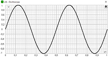
Take your first steps in using the labAlive environment. Adjust some scope settings and see how the scope displays the signal.
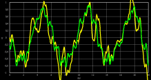
How does music or speech sound in different signal qualities? Recognize that it's the signal-to-noise ratio (SNR) that matters. Observe the visual and auditive impact of added noise.
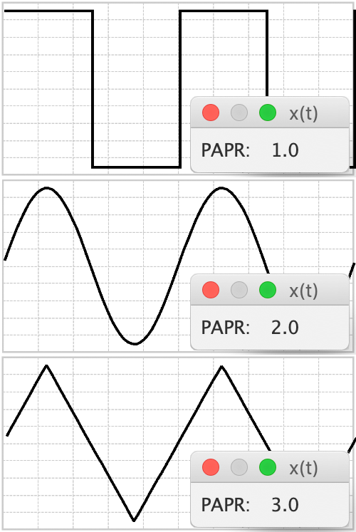
The Peak-to-average power ratio (PAPR) of a signal is the peak power divided by the average power.

Analyze audio signals in the time and frequency domain. Play any music wave file, microphone line-in or signal generator waveform. This audio software visualizes the signal in an oscilloscope and in a spectrum analyzer.
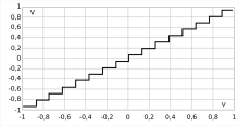
How does music or speech sound for different quantization resolutions? Explore how the quantization error degenerates the audio signal and each bit per sample improves the Signal-to-quantization-noise ratio by 6 dB.
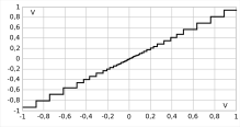
Explore how the use of compressors and expanders (companding) improves the signal quality compared to uniform quantization - especially for quiet voice. Logarithmic Laws - piecewise linear approximation.
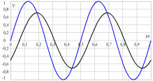
Measure amplitude and phase of the output sine wave signal using an oscilloscope. Compare the results with the transfer function representing the linear time-invariant (LTI) system.
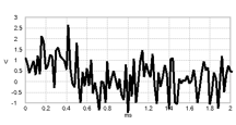
In this scenario, a pulse is sent and shall be detected at the receiver. It might represent a symbol for digital transmission or a radar pulse. The received pulse might be ...
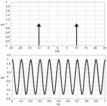
Explore the relationship of signals in the time and frequency domain. Adjust time parameters and see how the spectrum changes! Take a look at selected Fourier transform pairs of waveforms and pulses.
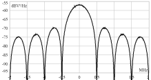
Control the settings of an FFT spectrum analyzer and get familiar with measurements in the frequency domain. Sampling time and capture time determine the spectrum's highest available frequency and resolution bandwidth.
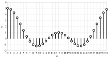
Calculate the FFT of signals. The FFT takes a time-discrete signal and computes the spectrum. Examples of time and frequency signals are shown, DC component, Dirac pulse, cosine, pulse, complex rotating phasor.
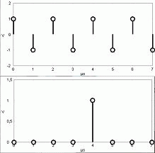
Calculate the Inverse Fourier Transform (IFFT). Enter a frequency-based signal and transform it to a time-based Signal.
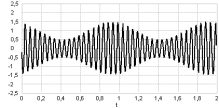
The invention of amplitude modulation made radio broadcasting possible. The message signal varies the carrier amplitude. Analyze an AM-signal in time and frequency domain and...
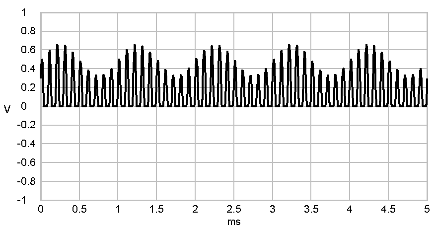
An easy way to recover the messsage signal of an AM-modulated signal is the envelope demodulator. In its simplest form the envelope...
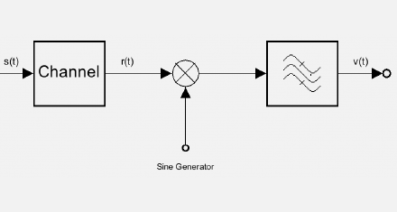
In AM transmissions without carrier a simple envelope detection is not possible. A more complex synchronous or coherent detection is required...
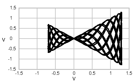
The amplitude modulation trapeze plots the modulated signal vs. the message signal including a DC offset that controls the carrier level.
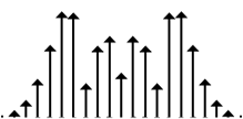
Frequency modulation signal spectra show sidebands for sinewave modulation. In this experiment we take a look how they change with the modulating signal amplitude.

Produce a frequency modulated transmission signal. Select music, speech, microphone or take your own audio file. Demodulate the signal using the FM receiver or let a USRP SDR transmit...

Demodulate the FM transmission signal. Listen to the received music or speech. Check if you modulated the audio signal properly and the frequency deviation is adjusted properly...
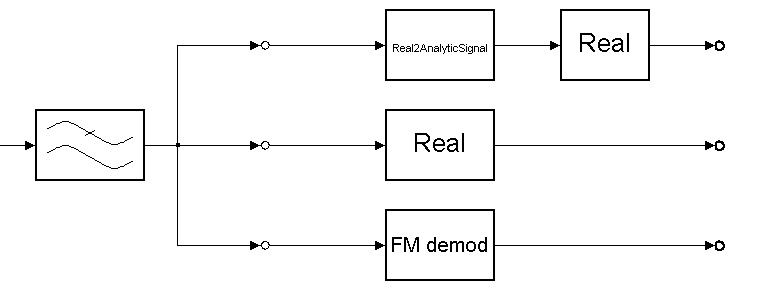
In this experiment, four-channel signals are available for practicing demodulation. Each of the channels is modulated in a different way.
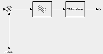
In order to deepen amplitude and frequency modulation and demodulation an experiment was designed.
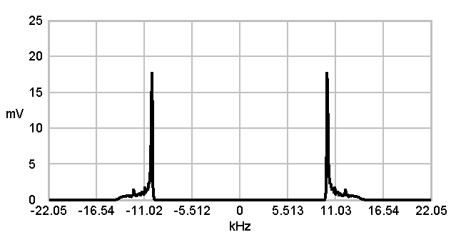
Amplitude modulation made radio broadcasting possible. Single sideband modulation made it possible to improve it, by saving bandwidth. Analyze a SSB-signal in time and frequency domain and change parameters...
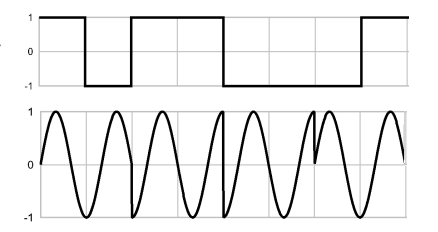
Comprehend how a QPSK signal is generated. Two bits are mapped to a symbol. Its phase shifts the carrier phase during the symbol duration.
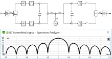
Explore hands-on how a QPSK signal is sent and demodulated. Check the transmission spectrum for different pulse shapers. Vary further parameters like carrier frequency etc.
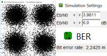
Explore the bit error rate for QPSK. Adjust Eb/N0 and measure the corresponding BER. Compare it to the analytical bit error probability. Vary the pulse shape - does it have effect on the BER?
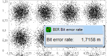
Analyse the bit error rate of M-QAM over an AWGN channel. Adjust Eb/N0 and the constellation size. Compare the measured BER to the analytical bit error probability.
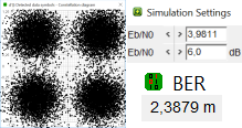
Measure the bit error rate for QPSK in high accuracy. Use this experiment to hands-on verify the analytical bit error probability as a function of Eb/N0. This app is optimized for high simulation speed.
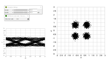
Explore how the Eb/N0 ratio affects the eye pattern and the constellation diagram. And how faulty is a transmission system where a terrible looking eye pattern is measured? Learn more about this topic and try the corresponding simulation experiment.
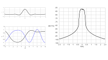
How can transmission signals be kept within the assigned bandwidth? Find out with this tutorial and try out some filter settings on your own.
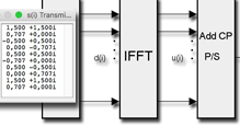
Understand OFDM and process each step using example values. A pilot sequence initializes the equalizer. Transmit an OFDM symbol and detect ISI-free.
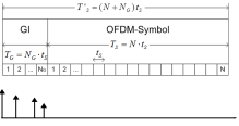
Explore how OFDM implements an ISI-free transmission and verify the required guard interval length for a multipath channel. Modify the delay spread of a fading channel and check the received signal points for ISI.
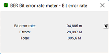
Verify the theoretical BER of IEEE 802.11ac OFDM setups with simulation results! Why does OFDM show an increased BER compared to single carrier systems in AWGN channel?
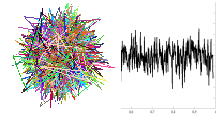
Why do OFDM systems show a high peak-to-average power ratio? How does the PAPR depend on the number of subcarriers? Has the underlying M-QAM constellation size any impact?
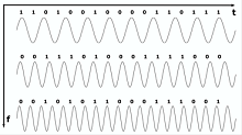
Learn the most important things about OFDM and its parameters. Show off your knowledge in the WiFi-parameter calculation exercise.
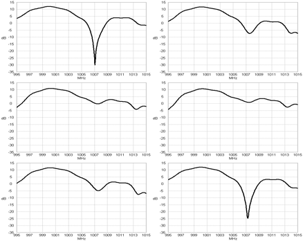
See how even small movements strongly impact frequency-selective channel characteristics. Fast fading describes mobile radio channels.
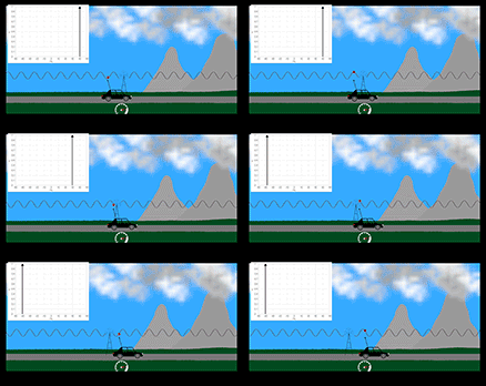
In channels where the receiver moves the signal frequency is shifted depending on the velocity. In practice the Doppler effect occurs in wireless communications.
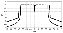
This simulation implements a Wi-Fi transmission (80 MHz, VHT-MCS 6, 400 ns guard interval). Analyze the signals, e.g. the transmit spectrum.
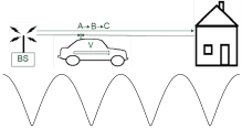
A direct path and a reflected path set up a simple multipath propagation environment. Determine the channel impulse response and transfer function!

A baseband equivalent representation of the channel is useful to process the transfer function around the carrier frequency. It's equivalent to the bandpass channel transfer function.

Analyze the bit error rate (BER) over an AWGN channel for QPSK and QAM. A calculator and a table help you finding out the values of Q(x) and erfc(x) depending on x.
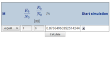
Calculate the M-ary QAM bit error probability in AWGN depending on energy per bit and the constellation size M.
This little tool helps you calculating logarithmic decibels into a linear power value and vice versa.
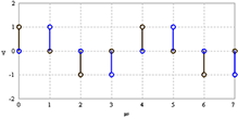
The power of the FFT output signal differs from the input signal power due to an asymmetry in the FFT / IFFT definitions. This FFT variant keeps input and output signal powers equal.

The power of the IFFT output signal differs from the input signal power due to an asymmetry in the FFT / IFFT definitions. This IFFT variant keeps input and output signal powers equal.
Here you can find all information about the Software you need to use the USRP - experiments. If you want to install all the Software and connect the USRP to your PC, you can find some information here too.

Use this experiment to receive a signal with your USRP and analyze it live or save it to a file

Use this experiment to send any analog signal like a sinus or square signal or to send music. This experiments uses frequency modulation (FM) to transmit a signal.
Use this experiment to send a signal from a file or receive a signal and save it into a file. This experiment doesn't use any modulation to send the signal.

In order to deepen amplitude and frequency modulation and demodulation an experiment was designed.

Placeholder for new experiment 4

Optical QPSK transceiver, coherent detection, homodyn, Optical Quadrature Phase-Shift Keying ...
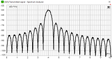
Start with your first steps to use the labAlive environment. Adjust some spectrum analyzer settings and see how the spectrum is displayed.
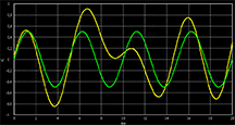
This demonstration shows example signals interfered by noise with variable bandwidth. The signal-to-noise ratio (SNR) is a measure for the signal quality. Visually evaluate the signal quality and noise bandwidth!

The two-path channel is a simple multipath propagation environment. Determine the channel impulse response and transfer function!
muss noch erstellt werden