myLabAlive - tutorial
In this section, you have the opportunity to create your very own and unique labAlive app, just as you wish. For this purpose, you can choose between various systems and filters, whose handling of which we will teach you in the following.
A simple showcase example is the following app.
 Code example
|
 System block: rectangular filter.
|
If you have already done some experiments, you know the basic structure of any app. In general, these consists of system blocks such as filters and generators and connection chains and their connecting elements. All of which, when assembled correctly, get illustrated in the block diagram and make up a runnable app.
The following is designed to give you a basic introduction to handling myLabAlive.
Source and Waveform
To launch an app, the first thing you need is a signal. Either you use a specific signal directly or a signal generator. The signal generator allows you to select any different type of signal by drop bar. It is also possible to insert and play audio files in the signal generator.


Additional sources can be found in our JavaDoc and as a pre-overview in the JavaDocIndex on the last page of this manual. In the latter, selected systems are also provided with linked examples for quick familiarization.
Systems
To process signals, to change them or to filter out certain frequencies, various systems such as high-pass and low-pass filters are utilized. An example for possible code is shown below.
 Code example
|
 System block: lowpass.
|
Your own app is perfectly capable of integrating other filters. Other available systems are summarized for you in the JavaDoc and again as a pre-overview in the JavaDocIndex on the last page of this manual. In the latter, selected systems are also provided with linked examples for quick familiarization. Feel free to have a look.
System chain
The individual system blocks in the app are connected with a dash. This is configured via "-" in the app. Therefore, the respective modules are separated from each other and it is possible to initialize them more precisely.

It is not important whether you use blank characters between the systems or not, this is up to you.
Multiple input
In order to combine several input signals, you can use connection elements such as adders or multipliers.


Multiple systems
Should you need several systems of the same type for your app, it is mandatory to number each one. Otherwise you will have problems explicitly addressing the right elements.
However there is no need to number the first system of its type as it will always start at 0. Starting from the second system you should be numbering them continuously. This is shown in the example below.
 |
 |
Variations
To modify an app according to personal requirements, the respective modules can be initialized directly using code. There are multiple variations, one that includes methods and another that doesn't. All output the same signal. Because of that, it is up to you how you program your app. To learn more about the methods check out the JavaDoc.
As shown below, it is possible to initialize the signal directly. To make everything clearer it is no problem to initialize the signal in separate lines. By using the shortcut setter and constructor it is possible to keep the initialization shorter.
 Different variations.
|
 Result of the different variations.
|
In this scenario, a sine signal was generated with a frequency of 5 kHz and an amplitude of 2V.
Example
Examples of different circuits are shown here. The code is next to it.
|
|
A signal generator is created here. This outputs a sine signal which must pass through a low-pass filter. |
 |
The corresponding app structure to the code. |


|
Here the example is shown once with the method calls and once without. The dirac signal and the delay were described once by setter method and once using shortcut setter and constructor in separate lines. Rect and gain just initialized inline with shortcut. |
 |
The corresponding app structure to the code. |
myLabAlive - examples
Within this section, a more detailed explanation of several applications is provided, offering a deeper understanding of their functionalities. Additionally, you have the option to directly perform experiments, allowing you to actively engage with the program and make adjustments according to your own preferences and requirements.
Your own app can be initialized in different ways, both interactively and hardcoded. Both options are presented below.
Interactively initialization
Probably the simplest and most visually method is the interactive app initialization, which does not require any deep hardcoding. Because many of the deep settings can be made in the running app as long as the basic setup of the circuit has been provided. This is presented in the following video. Your own user space can be reached via the following link -> myLabAlive Login.
Initialization by code
However, the process up to saving the settings shown in the video might prove too time-consuming for minor parameter adjustments, so a faster alternative with custom program code is desired. Therefore, as an alternative to the interactive initialization of a system, the app can also be defined directly using various methods, as the following three examples show. It does not matter for the final result which method you choose.
Label
To have a better overview in the app, you can additionally name each function. This makes it easier to identify different oscilloscopes in larger circuits.
The name of the respective system is described between the quotation marks. The changes can be seen at the respective images.
As already described, the scope is named exactly like the respective system. This makes it easier to distinguish between the different scopes.
Connection Line
In order to build larger apps it is usually necessary to have several connections on one module. This is possible by using multiple connection lines. This example briefly describes how exactly these work.
To start, a simple path with one connection line is created.
In the second example, another path is linked by an adder. This adds the signal from the lowpass with the additional signal.
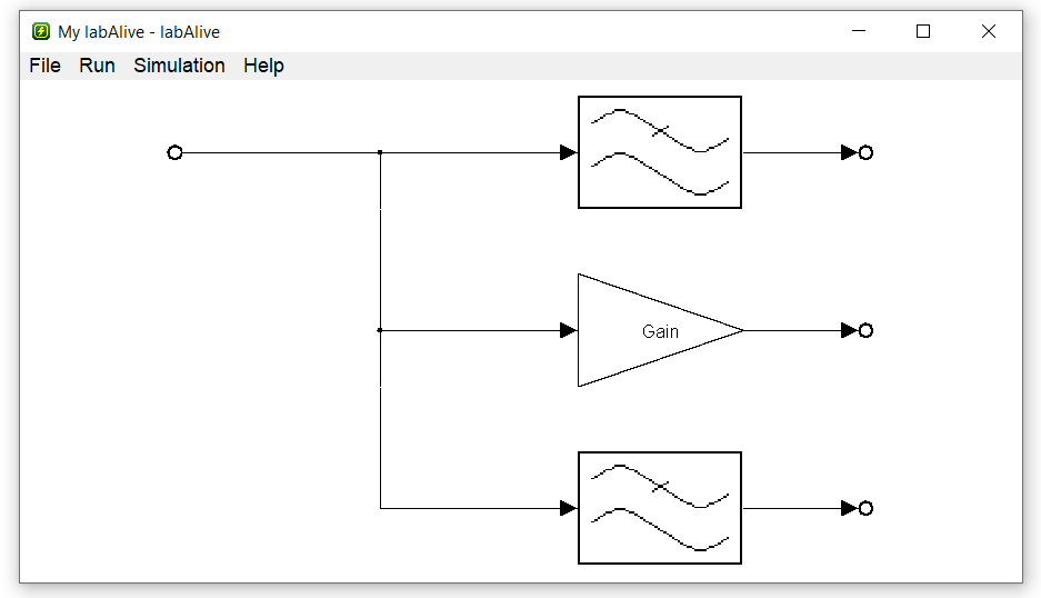
In the last example, the connection line is divided into three different paths. This allows for the modification of the input signal in three distinct ways.
Scope settings
To examine the signals in your own app more closely, it is possible to set the scope more precisely. The variables are used in exactly the same way as for the other blocks.
In this example, the scope settings were generally set to 0.5V spacing on the y-axis and to 0.2ms on the x-axis. In order to view the scope at the lowpass even more precisely, this specific scope was additionally set to a reduced y-axis spacing of 0.2V.
In the second example, we perform the same actions as in the first one. The distinction here is that the scope is opened directly. As demonstrated in this example, we have two commands: "set scope" and "show scope". Both commands configure the scope to the desired settings, but with "show", the scope is also immediately displayed on the screen for visual reference.
In addition, it is possible to customize the entire setup to a greater extent. Thus, the accuracy of the display can be adjusted as finely as possible to your own needs. Starting from "signalgenerator.scope" there are special settings for the diagram. This shows the scope of such precise control over the visual aspects of the display. However, these fine settings do not have to be programmed by oneself, but can also be realized interactively in the app and written out via the memory function (see introductory video at the beginning).
System Chain layout
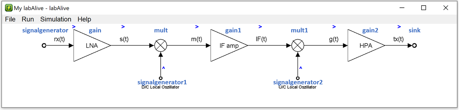
To design the layout of the system chain yourself, you can use additional characters to do so. By letters and characters like "v", "^", ">" and "<" you can set in which direction a certain system should continue to work. The following example shows the function . To learn more about the layout function continue in the tutorial till "Layout creation".
enum variable
Usage of enums: The system sinc method normalize is called with the parameter Normalization.MAX_IMPULS_RESPONSE. The enum type Normalization is detected automatically and the enum constant for MAX_IMPULS_RESPONSE is taken. Furthermore there are more forms of the type enum. Each of them specifies the respective constant of the specific type. To gain a deeper understanding and look up the remaining enums, you can examine the summary of the enum constant JavaDoc.
String function
It is also possible to include the string function in your own app. The example shows you how to use it.
JavaDoc index
| Block | Analog | Complex | Digital |
|---|---|---|---|
| Source |
CosMinusSineGenerator CosSineGenerator FileSignalSource SineGenerator SineGenerator |
AudioStereoSignalGenerator ComplexSource ManualInputComplexSource |
DigitalSource |
| System |
DopplerMultipathFading Upsample |
||
|
DownSample FmModulator JakesComplexMultipathFadingChannel OfdmSymbolDemux Parallel2Serial QPSKModulator QuadratureDemodulator SampleRateConverter Serial2Parallel |
AnalyticDemodulator AnalyticModulator ComplexDemodulator ComplexModulator EquivalentBasebandDemodulator EquivalentBasebandModulator FMComplexDemod FMComplexModulator IqSplitter IqSplitterShiftedInphaseBit IqSplitterQpsk QuadratureModulator SampleRateConverter |
AddVirtualSubcarrierSerial2Parallel BinaryDecider BitErrorRateMeter DownSample QuadratureDemodulatorOptical QuadratureModulatorOptical SampleRateConverter | |
| Filter |
IRR RectBandpass RectHighpass RootRaisedCosineFilter |
Fir2ComplexFir IIR |
DigitalFIR |
| Pulse |
ExponentialPulse GaussLowpass Sinc Sinc2 HalfSine MovingAverageFilter |
||
| Connector |
Multiplexer Sink |
||
|
Complex2Real Mux |
Complex2Real |
||
Further available blocks
Create your own app
Give it a try and see how easy it is to build a runnable app. Connect systems and start. labAlive text looks like a simple programming language.
To save your own app and edit it later, you can create an account on labAlive. Click here -> labAlive Login. This way it is also possible to share and provide apps with the community.
-
Start with a source. Type in a waveform to create a signal generator or any other source. (The first letters are sufficient, e.g. 'saw'.)
-
Type in ' - ' to indicate that you want to connect it to another system.
-
Continue with a system. Use any system name listed in JavaDoc index, e.g. 'lowpass' to create an instance (case insensitive). This serves a variable name refer to this system later on (case sensitive).
-
Optionally proceed with further systems. Finally a sink is automatically appended to terminate the system sequence.
-
All required parameters are set to default values and can be adjusted when the app is executed.
-
Set system attributes in an extra line in the format 'system method value'. Use the variable name of the system instance, e.g 'lowpass cutoffFrequency 20k'. Refer to the JavaDoc to see what setter methods the specific system offers.
-
Further system sequences can be defined in extra lines. It might terminate with a previously used multiple input system, e.g. an adder.
-
Split a system's output signal by connecting the same system to another.
-
Separate systems of the same type can be created by using the system's name with postfix '1', '2'...., e.g. lowpass1.
myLayout
To further improve the visual appearance of your app´s block diagram, you can enter layout commands in mylabAlive. For that you are going to learn two methods of how to create your own layout in myApps.
Combined method
The idea of this method is to define the layout within the connection of the systems. To properly connect the systems, it is important to use the desired directional instructions. Keep in mind to separate each block and its corresponding directional instruction with a space character. With these directional instructions you can position the systems in the wiring and they are defined as follows:
| Symbol | Meaning |
|---|---|
| ^ | one step up |
| < | one step left |
| v | one step down |
| > | one step right |
The following graphic provides an illustrative example of how a wiring layout is constructed using this method.
The connection of the systems combined with the layout would be:
Explicit method
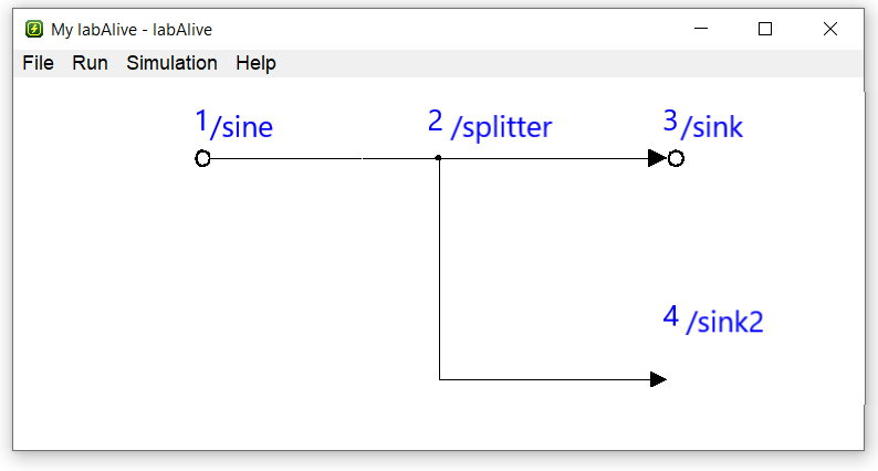
In contrast to the previous method, an explicit connection of the systems is necessary before defining the layout. For this, all systems are to be connected with a normal single dash "-". You must also address the systems in the layout definition with their index. In the following graphic you can see an example of how a layout of a wiring is built up with this method.
The layout-definition of this example would be: layout "1 > 2 > 3 > 4 > 5 > 6 > 7, 8 ^ 3, 9 ^ 5"
Below, you will find three examples showcasing different ways to implement a splitter. Following these examples, you will have the opportunity to complete an exercise.
First Example
In this example you can see the option to realize a splitter with the combined method. In this case the splitter is handled like a normal system.
Second Example
In the second example you can see one of two ways to realize a splitter with the explicit method. Here the splitter is also handled like a normal system.
Third Example
In this example you can see the second way to realize a splitter with the explicit method. It should be noticeable that the splitter is not clearly listed as a system as in the two previous examples, although it is still included. In this particular example, the splitter is labeled with the number 2 in the layout.
Advanced layout commands
To further refine the layout, graphical half-steps are also available as an option.
| Symbol | Meaning |
|---|---|
| w | half step up |
| a | half step left |
| s | half step down |
| d | half step right |
Exercise
In this exercise your job is to connect the systems and to create the layout of the following graphic on your own. You can find the names of the systems in the simulation description bellow but they are not sorted.
The systems are labelled as follows:
sine - split - split1 - lowpass - lowpass1 - gain - sink - sink1 - sink2