New experiments
- Further digital modulations like BPSK, OQPSK
- QAM pulse shaper and transmission spectra
- Eye diagrams in digital transmission
Backlog - potential new experiments
- Demodulate signals provided on server side. Find transmission signal in spectral range, adjust local carrier and select matching AM or FM demodulator
- Audio demonstration of diverse spectra. Quiz - listen to audio file and match corresponding spectra, e.g. white and band limited noise, mix of sine tones.
- Audio demonstration of dB levels. Quiz - listen to audio file and match db levels or dB differences of tones.
- myLabAlive - extend available block diagram layouts so that various user defined wirings can be displayed properly.
Backlog - potential new features
- Signal library on server side. Signal generator can use samples files provided by server, e.g. AM-, FM- or QAM modulated signals.
- Signal logger - extend to support wav file format.
Technical improvements
- Signal library on server side. Signal generator can use samples files provided by server, e.g. AM-, FM- or QAM modulated signals.
- Audio demonstration of diverse spectra. Quiz - listen to audio file and match corresponding spectra, e.g. white and band limited noise, mix of sine tones.
- Audio demonstration of dB levels. Quiz - listen to audio file and match db levels or dB differences of tones.
- myLabAlive - extend available block diagram layouts so that various user defined wirings can be displayed properly.
Quick Start
2.... System and measure adjustments
3.2..... Digital baseband
transmission
1 Hello world
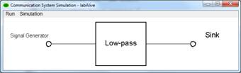
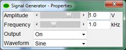
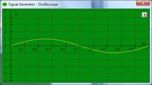
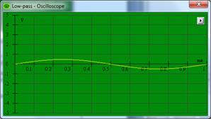
Figure 1: Sine wave input and its response. labAlive Simulations are connected
systems.

|
public class LtiSystem extends RunWiring { Source sigGen = new SignalGenerator(); System filter = new RectLowpass(1e3); System sink = new Sink(); public Source connect() { sigGen.connect(filter); filter.connect(sink); return sigGen; } } |
labAlive Wiring creates and connects systems: ·
Signal generator with default
settings. ·
Low-pass filter with cutoff frequency 1 kHz. ·
Sink. The three systems are
connected in a row. |
Listing 1: Java class setting up the simulation (Wiring).
When running this wiring, e.g. as Applet, the labAlive simulation engine
·
initializes
(creates and connects systems, creates measures ?)
·
lays
out, displays and
·
starts
simulating the wiring.
The simulation runs continuously.
·
The source produces signals.
·
They are fed into the low-pass filter.
·
It passes the output signals to the sink where they
terminate.
System
property and measure windows can be opened by left and right mouse clicks.
2 System and measure adjustments
The wiring
above uses default settings. Here specific adjustments are done.
Simulation
related settings:
·
System
parameters like amplitude and frequency.
·
Sampling
time
Display
related settings:
·
Wiring
name, i.e. title of the main window
·
Oscilloscope
and spectrum analyzer adjustments like AMPL / DIV and TIME / DIV
·
System
and Wire display labels
|
public class LtiSystemX extends RunWiring { Source sigGen = new SignalGenerator().amplitude(1d).frequency(2e6).samplingTime(1e-9); System filter = new RectLowpass(2e6); System sink = new Sink(); public Source connect() { sigGen.connect(filter); filter.connect(sink); return sigGen; } @Override public void configure() { gui.wiringName = "Linear time-invariant System"; osci = new Osci().amplitude(200e-3).time(1e-7); spectrum = new Spectrum().amplitude(0.05).frequency(1e6); }
@Override public void label () { sigGen.getOutWire().label("x"); filter.label("Treble cut"); filter.getOutWire().label("y"); } } |
Listing 2: Do explicit simulation and display adjustments.
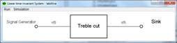
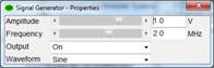
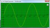
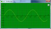
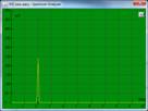
Figure 2: Specific system and measure settings. ![]()
|
|
|
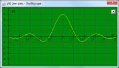
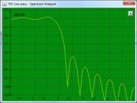
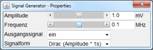
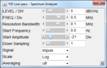
Figure 3: Impulse response and frequency characteristic after some manual
adjustments via GUI.
3 Example Applications
3.1 Matched filter
This wiring
uses the following features:
· Digital and analog signals
· Up- and downsample
·
System switch ? the active
pulse shaper implementation can be changed at runtime
·
Several
signal sources (digital signal generator and noise).
·
Multiplex
wire connecting a system output to several systems
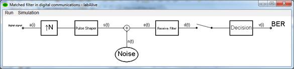
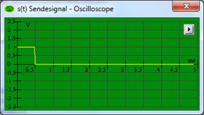
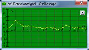
Figure 4: Matched filter ? maximum signal-to-noise ratio signal detection
![]()
![]()

Figure 5: An optimal SNR of 1V2 / 25mV2 = 40 is determined
- in theory the SNR is E / Lo = 0,5 mV2s
/ 12,5 mV2s = 40. The optimal receive filter and down sampling point
must be set. The signal and noise power is measured separately by turning
either noise or signal off.
|
public class MatchedFilter extends RunWiring { SamplingTime samplingTime = getSamplingTime(); double systemBandwith = 1.0e3; DigitalSignalGenerator digitalSource = new DigitalSignalGenerator(ONES); System upsample = new Digital2AnalogUpsample(samplingTime.getSamplesPerBit()); DownSample downSample = new DownSample(samplingTime.getSamplesPerBit(), 30); SystemSwitch pulseShaper = new SelectablePulseShaper(systemBandwith, GaussianNoise noise = new GaussianNoise(POWER_SPECTRAL_DENSITY).power(12.5e-6); System adder = new Adder(); SystemSwitch matchedFilter = new SelectablePulseShaper(systemBandwith,LOWPASS_SPECTRUM); System binaryDecider = new BinaryDecider(); BitErrorRateMeter bitErrorMeter = new BitErrorRateMeter(); public Source connect() { digitalSource.connect(upsample); digitalSource.connect(bitErrorMeter); upsample.connect(pulseShaper); pulseShaper.connect(adder); noise.connect(adder); adder.connect(matchedFilter); matchedFilter.connect(downSample); downSample.connect(binaryDecider); binaryDecider.connect(bitErrorMeter); return digitalSource.samplingTime(samplingTime.getBitDuration()); } protected SamplingTime getSamplingTime() { return new SamplingTime(20e-6, 5E-3); } @Override
public void
configure() { gui.wiringName = "Empfangsfilter
bei Digitalübertragung"; gui.mainWindow.size = new RelativeSize(50, 25); } @Override public void adjustMeasures() { osci = new Osci().amplitude(0.5d).time(samplingTime.getBitDuration() / 10); matchedFilter.getOutWire().set(osci.show()); spectrum = new Spectrum().amplitude(0.01).frequency(500d).resolutionBandwidth(20d); }
} |
Listing 3: Matched filter
3.2 Digital baseband transmission
This wiring
uses the following features:
· Extend an existing wiring
·
Eye
pattern oscilloscope display assigned to specific wire
·
Bit
error rate meter
|
public class DigitalBaseband extends MatchedFilter { static final long serialVersionUID = 1007L;
@Override protected SamplingTime getSamplingTime() { return new SamplingTime(20e-6, 0.5E-3); } @Override public void configure() { gui.wiringName = "Digital baseband transmission"; } @Override public void doAdaptations() { super.doAdaptations(); digitalSource.mode(Mode.RANDOM); noise.power(5E-5).on(); pulseShaper.setCurrentSystem(RootRaisedCosineFilter.class); matchedFilter.setCurrentSystem(RootRaisedCosineFilter.class); downSample.setStepOfSample(0); bitErrorMeter.setInputDelay(4); } @Override public void adjustMeasures() { osci = new Osci().amplitude(0.5).time(samplingTime.getBitDuration() / 5d); matchedFilter.getOutWire().set(osci.amplitude(0.2d).display(EYE_PATTERN).show()); digitalOsci = new DigitalOsci().time(samplingTime.getBitDuration()); } } |
Listing 4: ? Digital baseband transmission ?
|
|
|
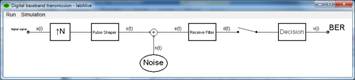
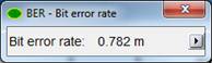
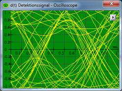
Figure 6: Digital baseband transmission with bit error meter. In theory the bit
error rate is 0.783 e-3 for this SNR of 10.
Master thesis
J. KrĂĽger, "Kommunikationstechnische Anwendungen fĂĽr labAlive Web und App", Institute of Wireless Communications, Universität der Bundeswehr München, 2023.
R. Herbst, "Entwicklung von Features zur Verzahnung von labAlive Web- und App und Suchfunktion", Institute of Wireless Communications, Universität der Bundeswehr München, 2023.
F. Schäfer, "Wireless Communications Experimente mit labAlive", Institute of Wireless Communications, Universität der Bundeswehr München, 2021.
J. Döing, "Software Defined Radio für Simulationsumgebung labAlive - Anbindung und Anwendungen", Institute of Wireless Communications, Universität der Bundeswehr München, 2021.
R. Wiesner, "Blockdiagramm Layout von labAlive-Simulationen. Konzepte und Anwendungen", Institute of Wireless Communications, Universität der Bundeswehr München, 2020.
N. Lorenzen, "Online Editor zum Online Erstellen von labAlive Simulationen", Institute of Wireless Communications, Universität der Bundeswehr München, 2019.
H. Petersen, "Interaktive Konfiguration und Speicherung von labAlive Simulationen", Institute of Wireless Communications, Universität der Bundeswehr München, 2019.
S. Niendorf, "Layout Generator und GUI Erweiterungen für labAlive Blockdiagramme und Fenster", Institute of Wireless Communications, Universität der Bundeswehr München, 2019.
P. Tholl, "WDF-Messgerät und Parametrisierung von Messgeräten für die labAlive Simulationsumgebung", Institute of Wireless Communications, Universität der Bundeswehr München, 2019.
D. Nolde, "Paradigm Examples of Online Experiments for a Virtual Communications Lab", Institute of Wireless Communications, Universität der Bundeswehr München, 2019.
Bachelor thesis
N. Dombek, "Weiterentwicklung und Websecurity des labAlive Identity- und Accesmanagements", Institute of Wireless Communications, Universität der Bundeswehr München, 2023.
L. Stöckl, "Weiterentwicklung der LabAlive-Webanwendung mit Schwerpunkt Websecurity", Institute of Wireless Communications, Universität der Bundeswehr München, 2023.
B. Röckert, "Weiterentwicklung der labAlive Anwendung", Institute of Wireless Communications, Universität der Bundeswehr München, 2023.
L. A. Simon, "Entwicklung von Komponenten einer IDE fĂĽr die LabAlive-App myApps Webanwendung", Institute of Wireless Communications, Universität der Bundeswehr München, 2023.
D. Hirlimann, "Entwicklung einer Code-Validierung fĂĽr labAlive myApps aus Sichtweise der Cybersecurity", Institute of Wireless Communications, Universität der Bundeswehr München, 2023.
M. Frank, "Repository fĂĽr labAlive - Parametrisierter Aufruf von Simulationen", Institute of Wireless Communications, Universität der Bundeswehr München, 2022.
J. P. Peschek, "Online Experimente zu analogen Modulationsverfahren", Institute of Wireless Communications, Universität der Bundeswehr München, 2021.
T. Stelz, "Online Experimente zu optischen Modulationsverfahren", Institute of Wireless Communications, Universität der Bundeswehr München, 2021.
W. Zimmermann, "Einbindung des Software Defined Radios in die Simulationsumgebung LabAlive", Institute of Wireless Communications, Universität der Bundeswehr München, 2019.
E. Riederer and R. Matzner, "labAlive-a Java toolbox for the simulation of systems," Proceedings IEEE International Conference on Multimedia Computing and Systems, Florence, Italy, 1999, pp. 836-840 vol.2, doi: 10.1109/MMCS.1999.778595. See also IEEE Xplore.
labAlive - A Java Toolbox for the Simulation of Systems. 2000