 To launch labAlive simulation applications you need a Java Runtime Environment supporting Java Web Start on your system. Here you can get more information about installing the right Java version.
One of the most important aspects in communication technology is
keeping the signal, that has to be transmitted, within the assigned
bandwidth. This is essential to prevent the transmission from being
disturbed by its spectral neighbors and the other way around. This is
where pulseforming has to be taken into consideration. A scale for the
quality of a transmission is its Nyquist Bandwidth. In case of a QPSK
modulated signal with a datarate of 1 Mbit/s the Nyquist Bandwidth is
0.5 MHz. This bandwith is the minimum that is necessary for the
transmission. Otherwise the signal can not be detected properly anymore
in the receiver.
The following picture shows a
rectangular pulse created by a signal source with a transmission rate
of 1 MBit/s.
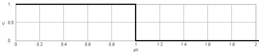
Due to the modulation of the signal with a QPSK modulator, the length
of the single pulses is 2 times of one bit duration. As you may know, sharp edged signals
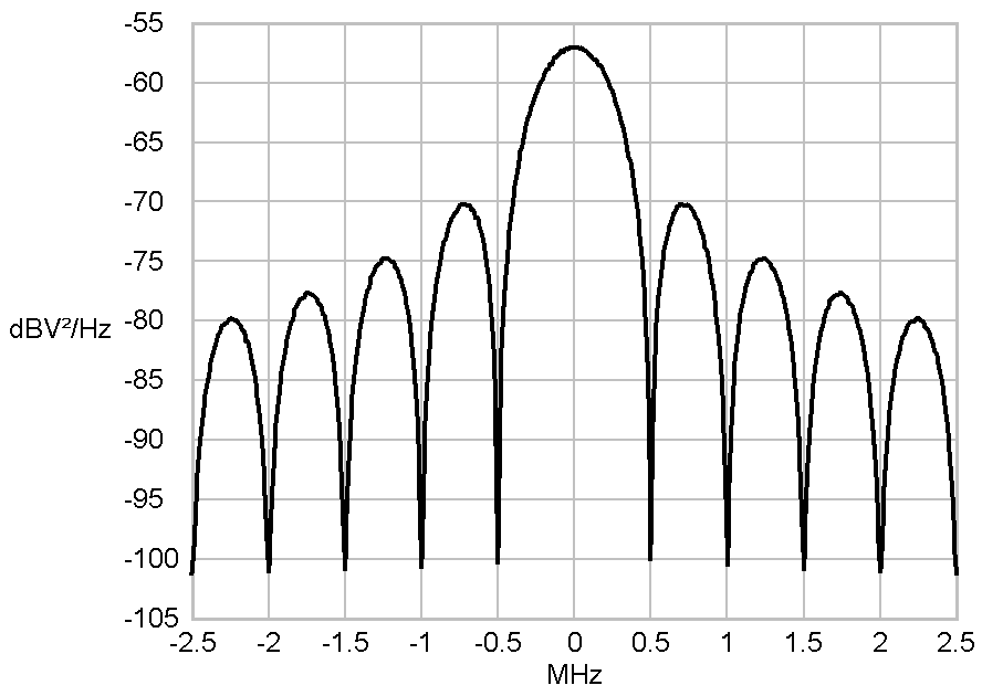
contain sine and cosine waves with high frequencies and high amplitude.
This is why the spectrum of a signal, which consists of rectangular
pulses, shows a extraordinary high powers beyond the Nyquist Bandwidth
(-0.25 MHz - 0.25 MHz in this case). The necessary bandwith of a
transmission can be manipulated by the application of filters.
Have a look at the images in the slideshow below to see the
differences between rectangular shaped pulses, halfsine shaped pulses,
sinc shaped pulses and root raised cosine pulses.


Having a look at the graphs of a transmission with halfsine shaped
pulses you can see, that the central part of the spectrum may indeed
require a larger bandwidth in comparison to a rectangular pulseshaped
transmission, but in the area beyond -1 MHz and 1 MHz the powers fade
away much earlier. Changing the shape of the basic pulse into a sinc
shape nearly completely removes signal parts beyond +-0.5 MHz around
the center of the signal. But this removal of high frequency signal
components can lead to intersymbol interference (ISI)
when filter length is limited.
Another option for a pulse-shaping filter is a
filter with a root raised cosine (RRC) frequency
response. that provides signal pulses. These filters are the most
common filters in communication technology because they fulfill the
criterions for a intersymbol interference (ISI) free transmission.
By tuning a digital root raised cosine filter in filter
length the result can be enhanced much further. Check out the
corresponding experiment and find out how different pulseshapers and a
variation of their parameters affect the transmission.
1. Launch the Simulation
Click on the launch button to start the simulation. The block diagram and some control windows will show up.
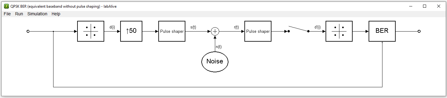
2. Open Spectrum Analyzer
Right click on the signal path between the sender pulse shaper and the plus symbol where the noise is added. "Select Spectrum Analyzer". The analyzer window that shows the transmission spectrum will show up.
3. Vary the pulse shaper settings and monitor the transmission spectrum
By right clicking on the pulse shaper and the selection of "select system" in the appearing menu the filter can be changed. Try some different filters and watch how they affect the transmission spectrum. Left clicking on the pulseshaper opens a control window where filter parameters can be adjusted.

Basic pulse created by a rectangle
pulseformer
|

Power-density spectra of a
rectangle shaped Symbol
|

Amplitude over time plot of a
Symbol after being filtered by a halfsine-shaped pulseformer
|

Power-density spectra of a
halfsine shaped Symbol
|

Amplitude over time plot of a
Symbol after being filtered by a sinc-shaped pulseformer
|

Power-density spectra of a sinc
shaped Symbol
|

Amplitude over time plot of a
Symbol after being filtered by a root-raised-cosine-shaped
pulseformer
|

Power-density spectra of a
root-raised-cosine shaped Symbol
|