 To launch labAlive simulation applications you need a Java Runtime Environment supporting Java Web Start on your system. Here you can get more information about installing the right Java version.

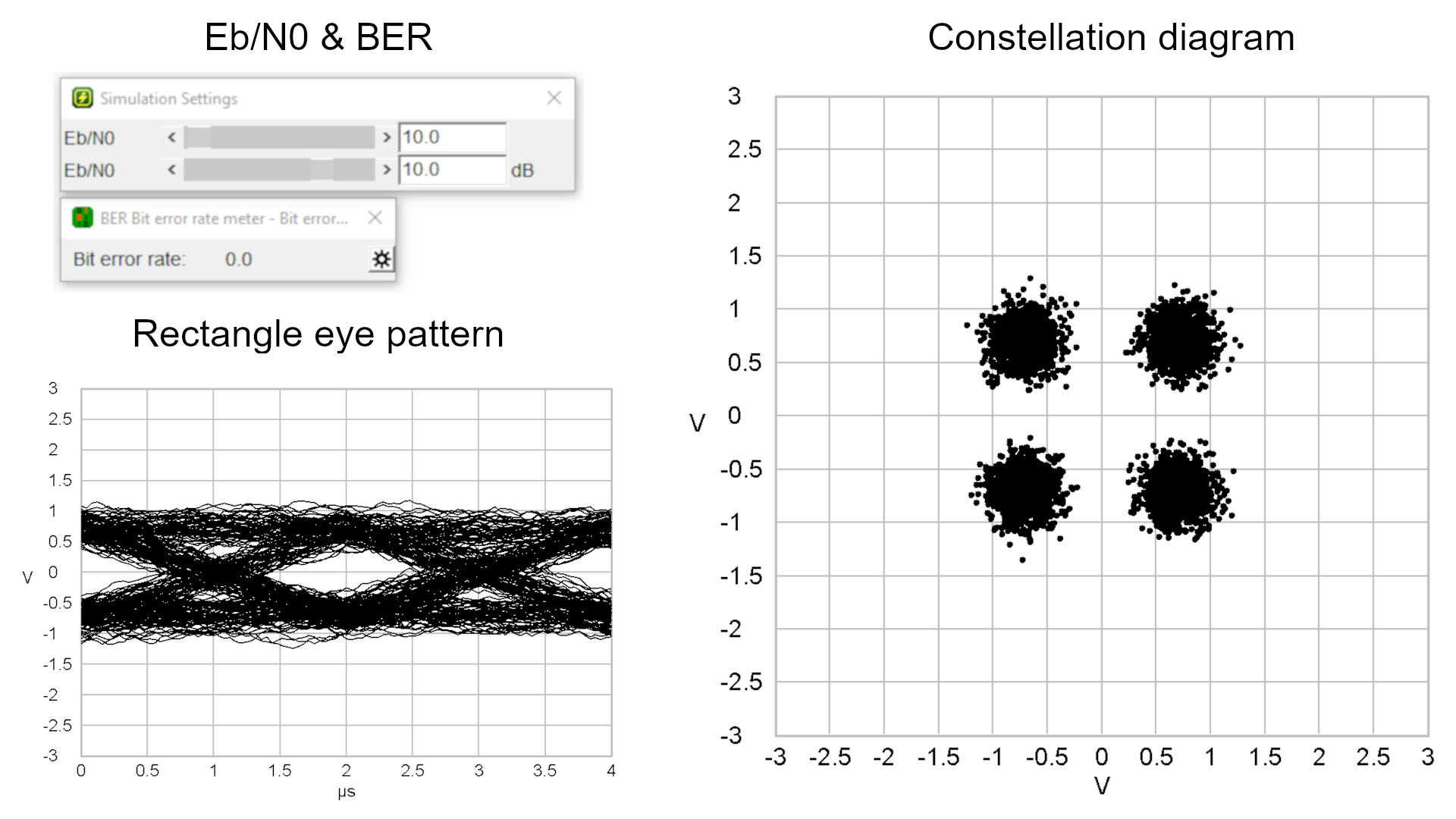
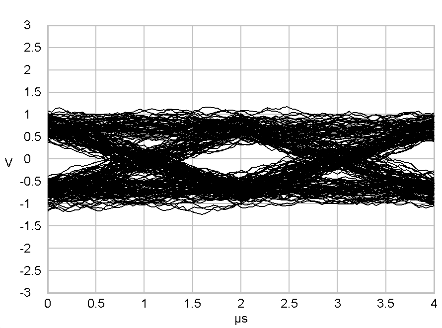
When it comes to evaluating the quality of a digital transmission, the bit error rate can be utilized. To measure the BER, a known testsignal has to be transmitted and compared with the received data. The ratio of wrong bits in the receiver is the mentioned bit error rate. Another way to get information about the quality of a transmission is the monitoring of the so called eye-pattern. The eye-pattern can be described as a oszilloscope that keeps showing all traces. Executing such a measurement with the received signal of a digital transmission will produce a picture that contains all possible condition transitions. A transmission with a S/N ratio of 10 dB leads to the following result:
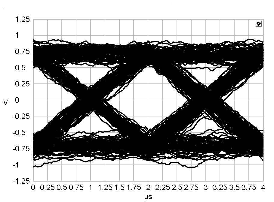
As you can see, the eye-pattern reveals a clearly visible eye opening
without any signal paths interfering with eachother in the area of
detection sampling (center part of the diagram). The contained noise in
the received signal causes the traces of the eye pattern to slightly
vary in amplitude. Nevertheless, a transmission with this eye-pattern
is what can be called a extraordinary good transmission due to the
clearly visible eye opening. Having a look at the measured BER of this
system confirms the estimated quality. The BER of this transmission is
approximately 0, so all sent bits will be detected correctly.
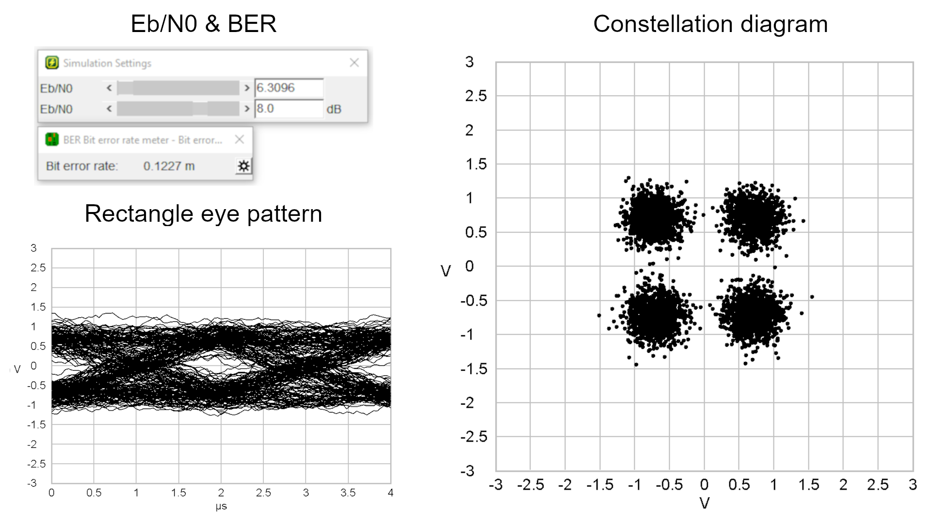
Decreasing the signal to noise ratio of the transmission
system affects both the bit error rate and the appearance of the
eye-pattern.
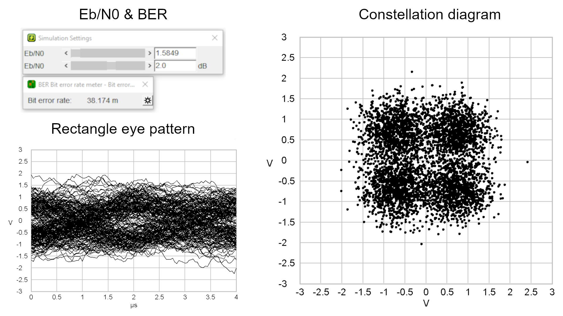
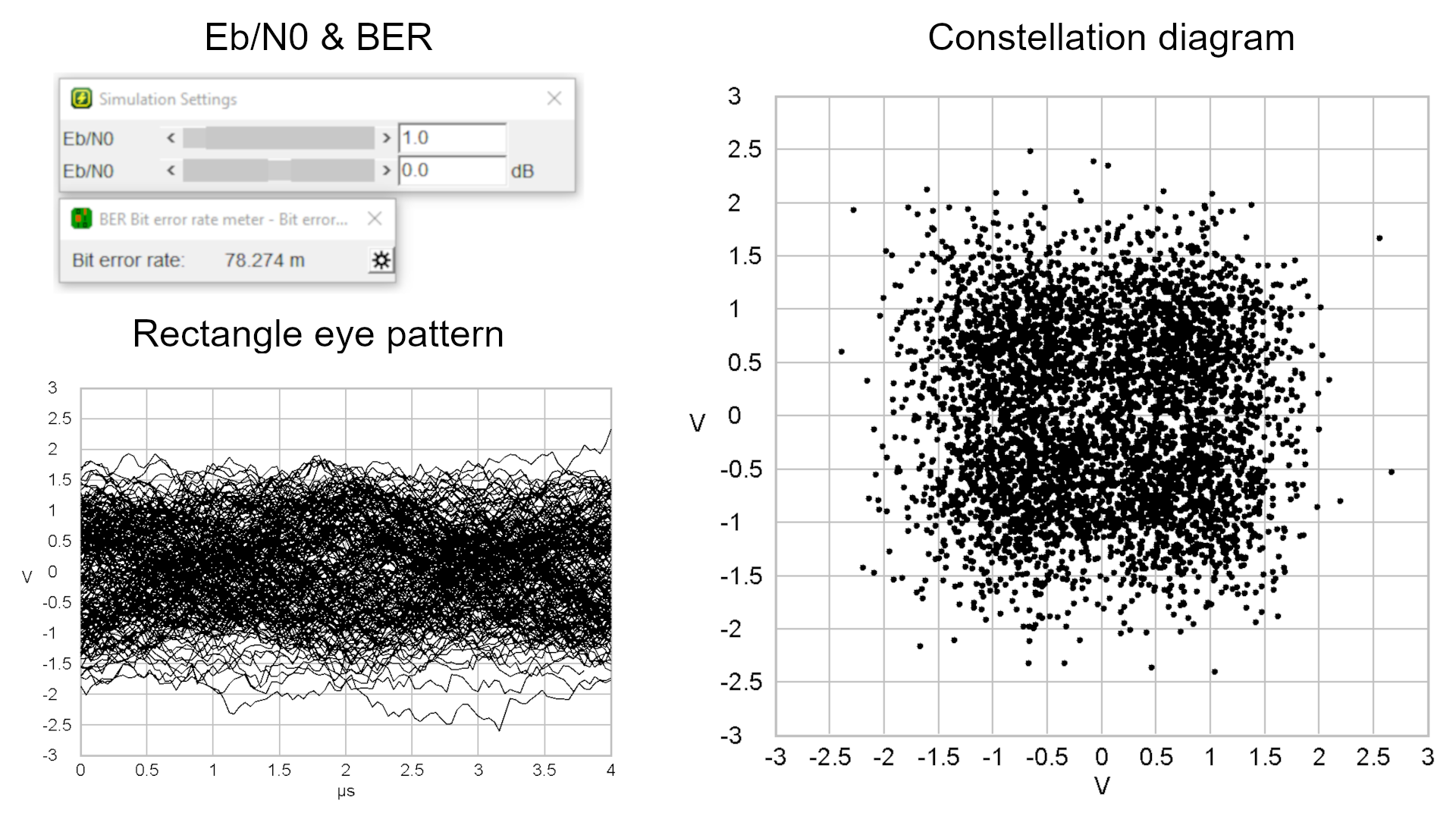
The slideshow above contains eye patterns and constellation diagrams of
transmissions which differ in Eb/N0 ratio or pulseshaping filter. If
they are compared with each other the diagrams show obvious
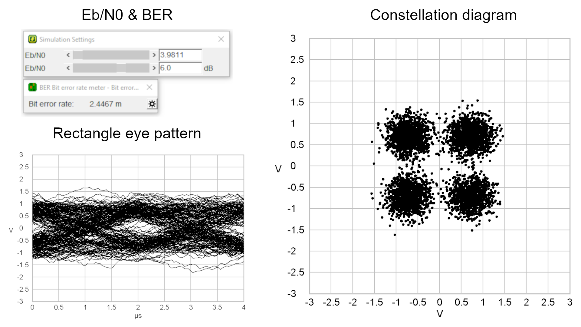
differences. Some of them, for example a transmission with a Eb/N0
ratio of 6 dB show a wide spread of the single traces and even some
traces in the center area of the diagram. These traces are the result
of the relatively higher noise in the signal and can lead to a wrong
detection in the receiver. This is why the BER of a transmission with a
Eb/N0 ratio of 6 dB was measured as 2.4E-03.
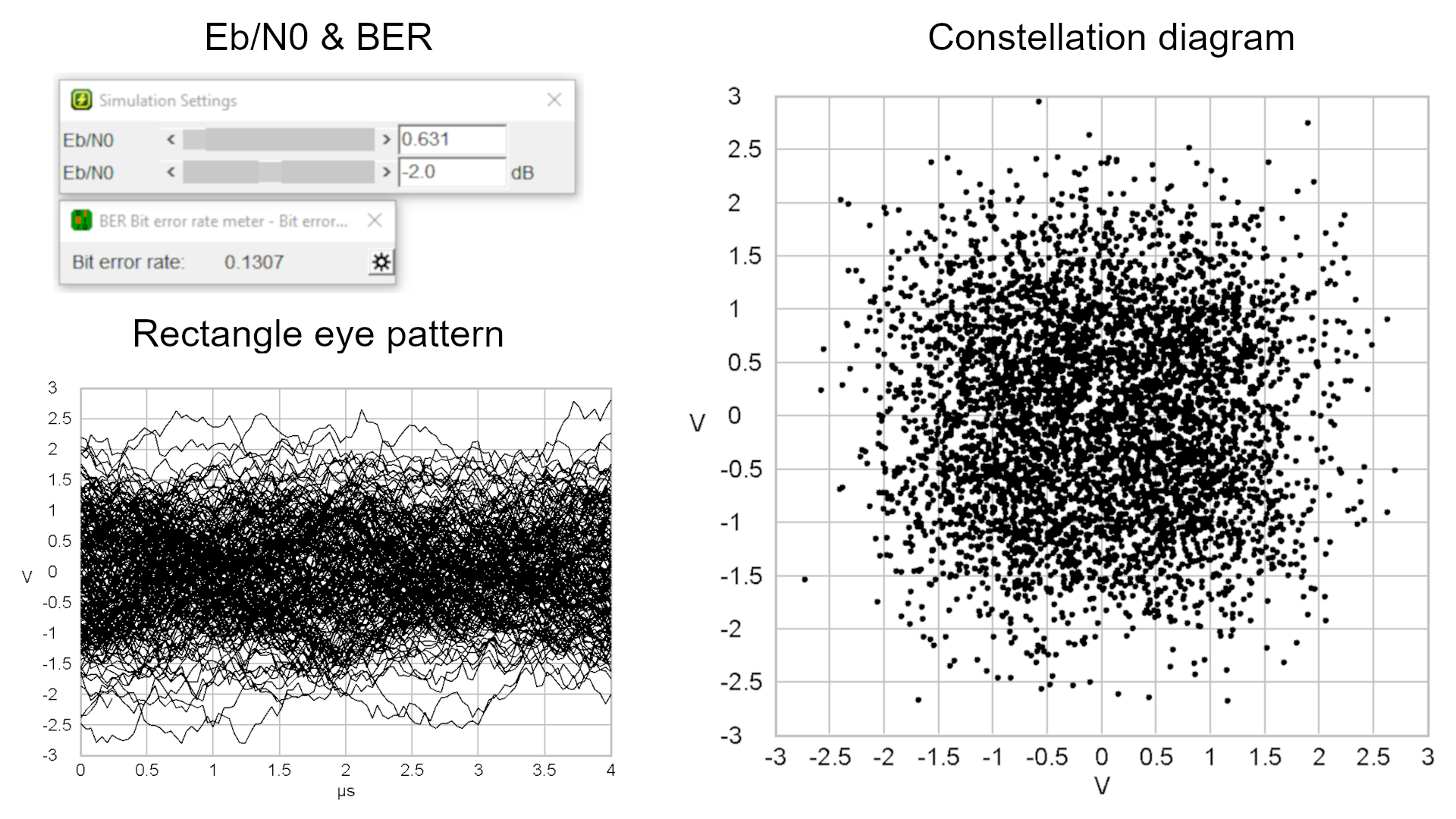
Knowing this, only a short look at the picture which shows the
eye-pattern and the constellation diagram of a transmission with a
signal to noise ratio of -2dB should be enough to understand that this
must be a quite bad transmission. The eye-pattern is barely
recognizable and absolutely no eye opening can be seen. Also the dots
of the constellation diagram are spread all over the diagram. But
interestingly, even though the eye-pattern looks this kind of bad, the
BER of this system is with 0.13 not as bad as you maybe would expect.
Check out the corresponding experiment to generate some eye-patterns and constellation diagrams on your own and have a look at the illustration-page for more vividly content.
1. Launch the Simulation
Click on the launch button to start the simulation. The block diagram and some control windows will show up.

2. Open the oscilloscope
Click on the path of the receive signal between the receive filter and the sampler to open a oscilloscope. The diagram shows the eye pattern of the signal after passing the AWGN channel, so noise is included.
3. Open the constellation diagram
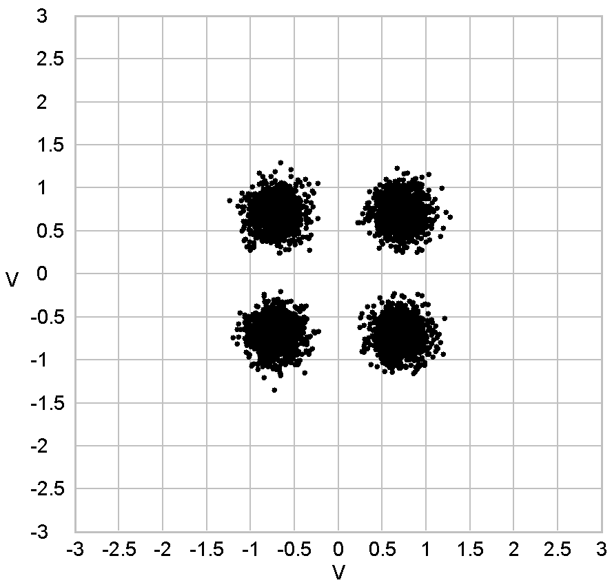
Right click on the path of the receive signal between the sampler and the decider (dŽ(i)). Choose the constellation diagram.
4. Vary the S/N ratio and monitor the eye-pattern
Try different signal to noise ratios and watch how they affect the eye-pattern. Also have a look at the bit error rate.
5. Vary the pulseshaper and monitor the eye-pattern and constellation diagram
Click on the "Simulation" button in the left top corner of the block diagram window. Choose "Setup" and select another pulse shaping filter in the appearing window than a rectangular one.
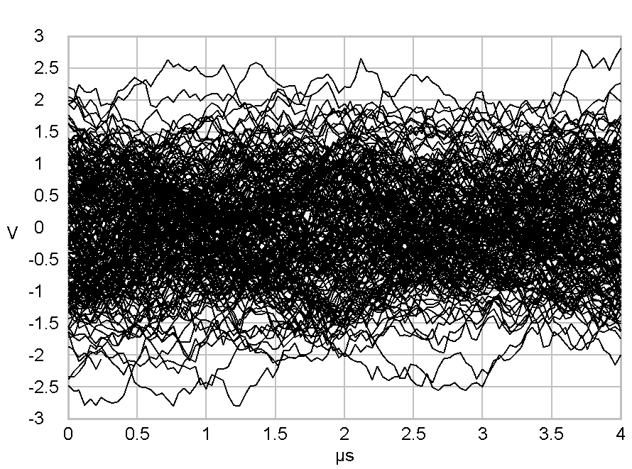
Eye-Pattern at -2 dB S/N ratio
which results in a BER of 0.13
|
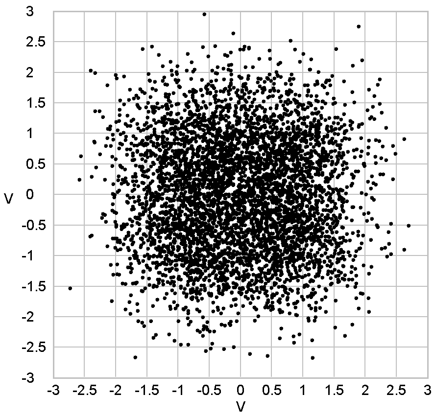
Constellation diagram at -2 dB S/N
ratio.
|
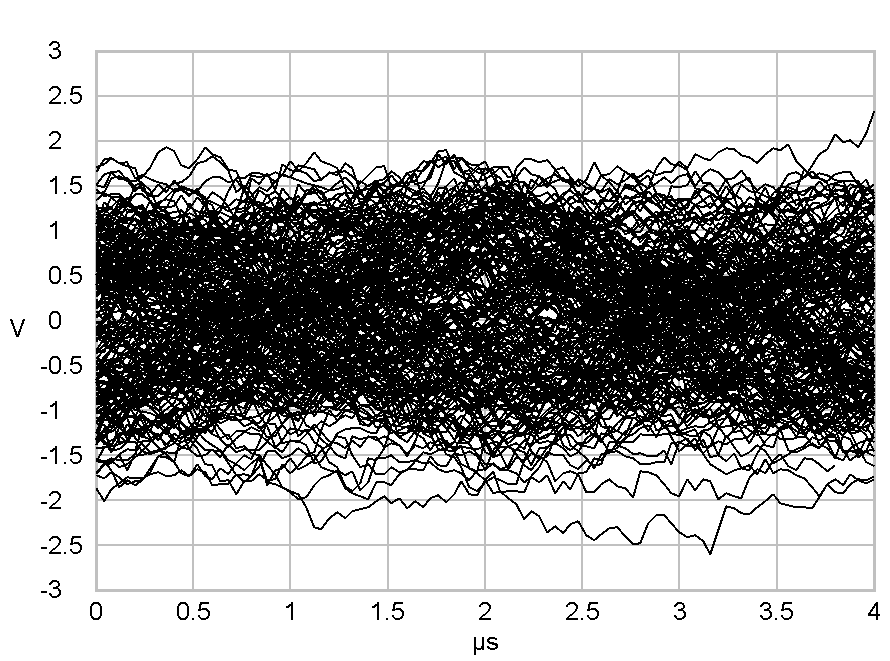
Eye-Pattern at 0 dB S/N ratio
which results in a BER of 78E-3
|
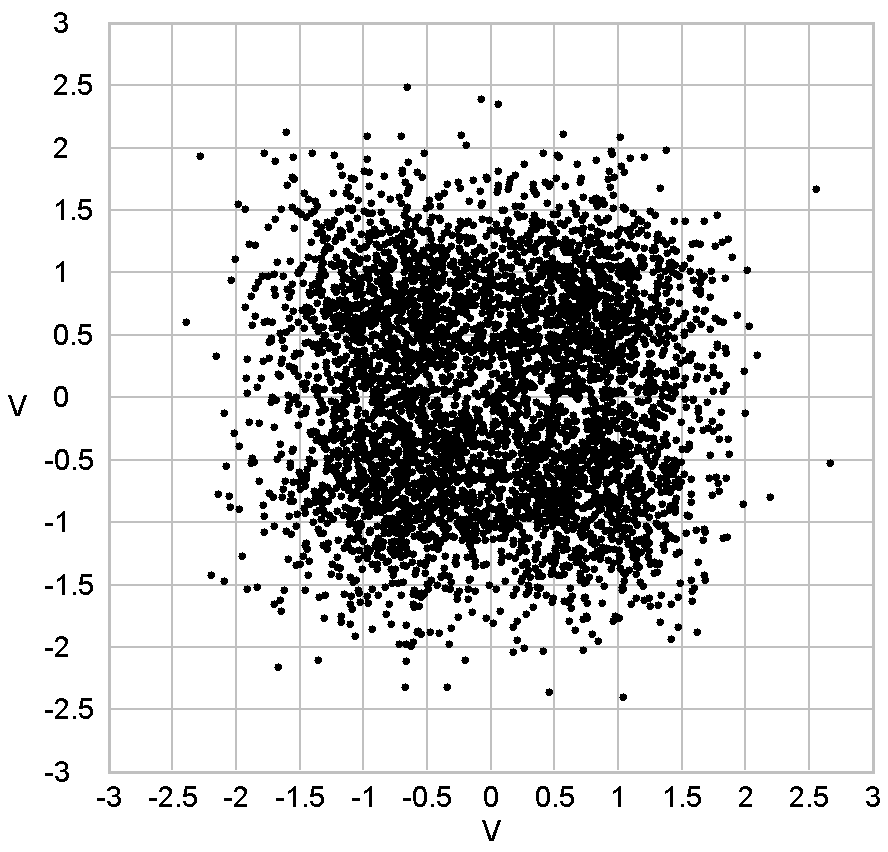
Constellation diagram at 0 dB S/N
ratio.
|
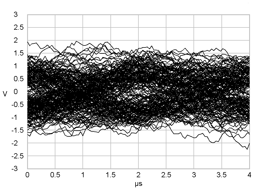
Eye-Pattern at 2 dB S/N ratio
which results in a BER of 38E-3
|
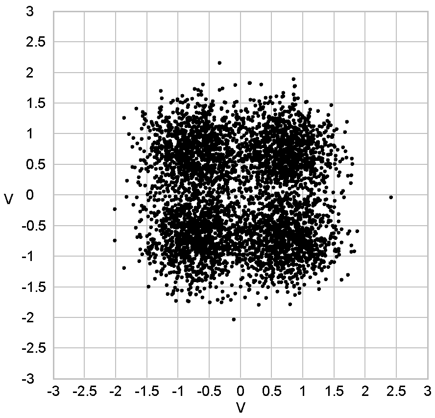
Constellation diagram at 2 dB S/N
ratio.
|
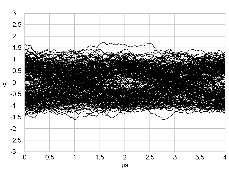
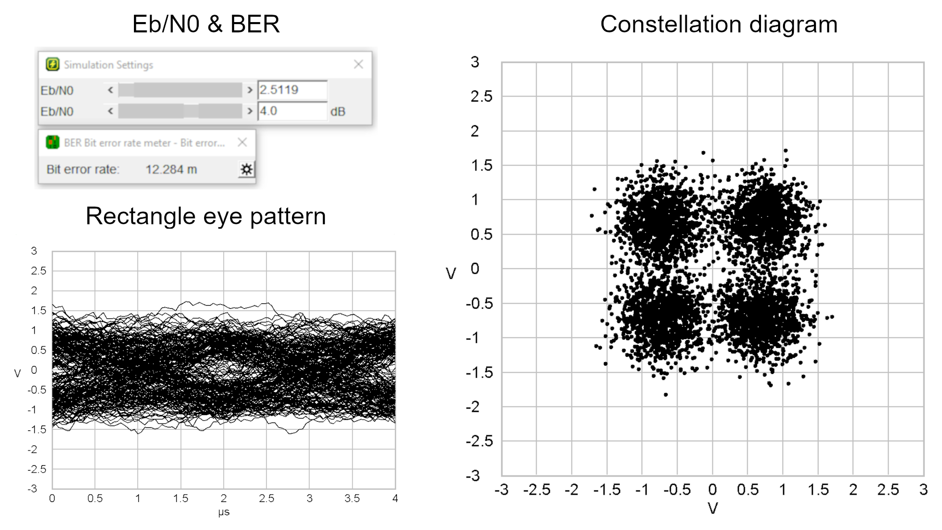
Eye-Pattern at 4 dB S/N ratio
which results in a BER of 12E-3
|
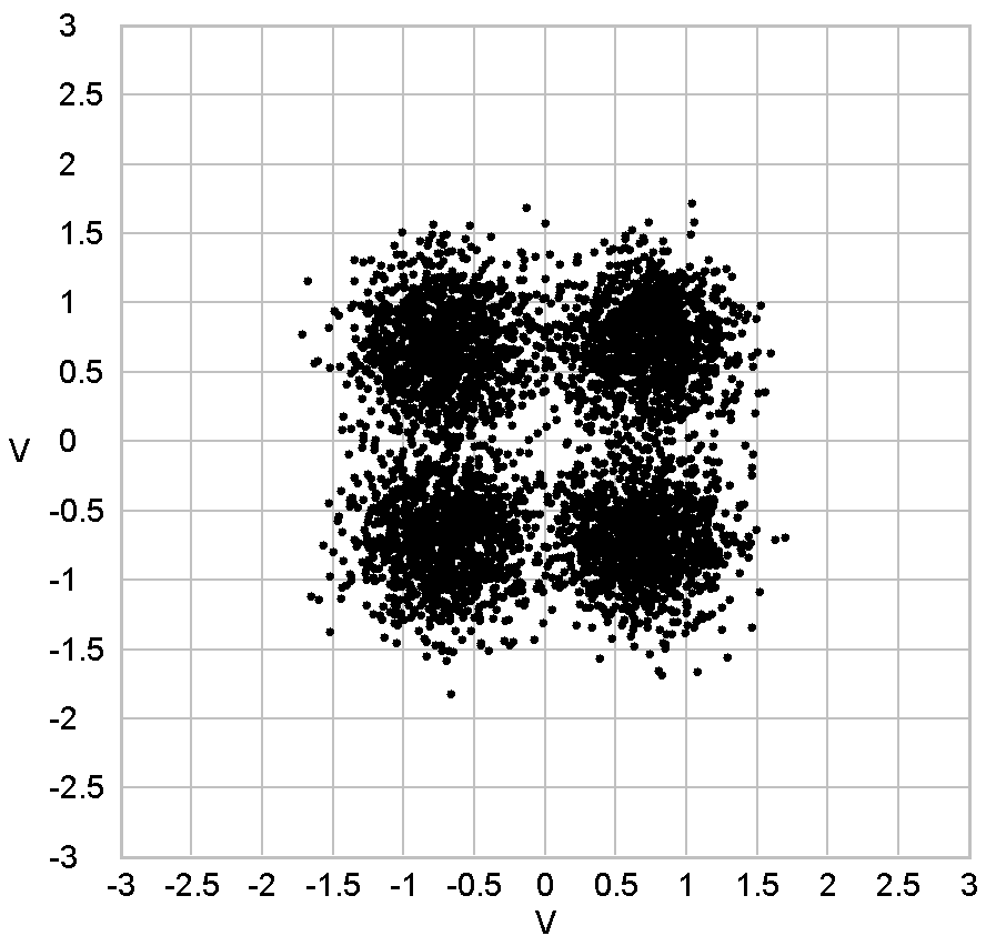
Constellation diagram at 4 dB S/N
ratio.
|
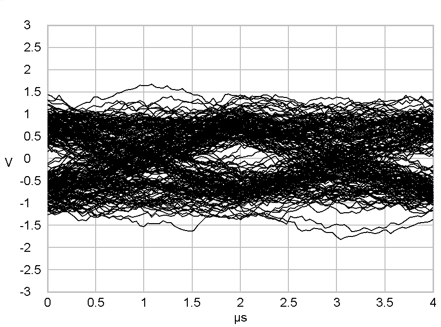
Eye-Pattern at 6 dB S/N ratio
which results in a BER of 2.4E-3
|
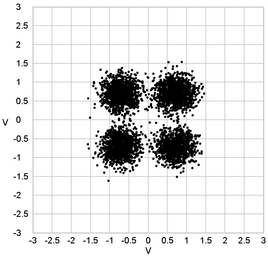
Constellation diagram at 6 dB S/N
ratio.
|
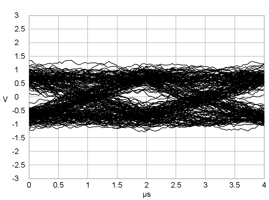
Eye-Pattern at 8dB S/N ratio which
results in a BER of 0.12E-3
|
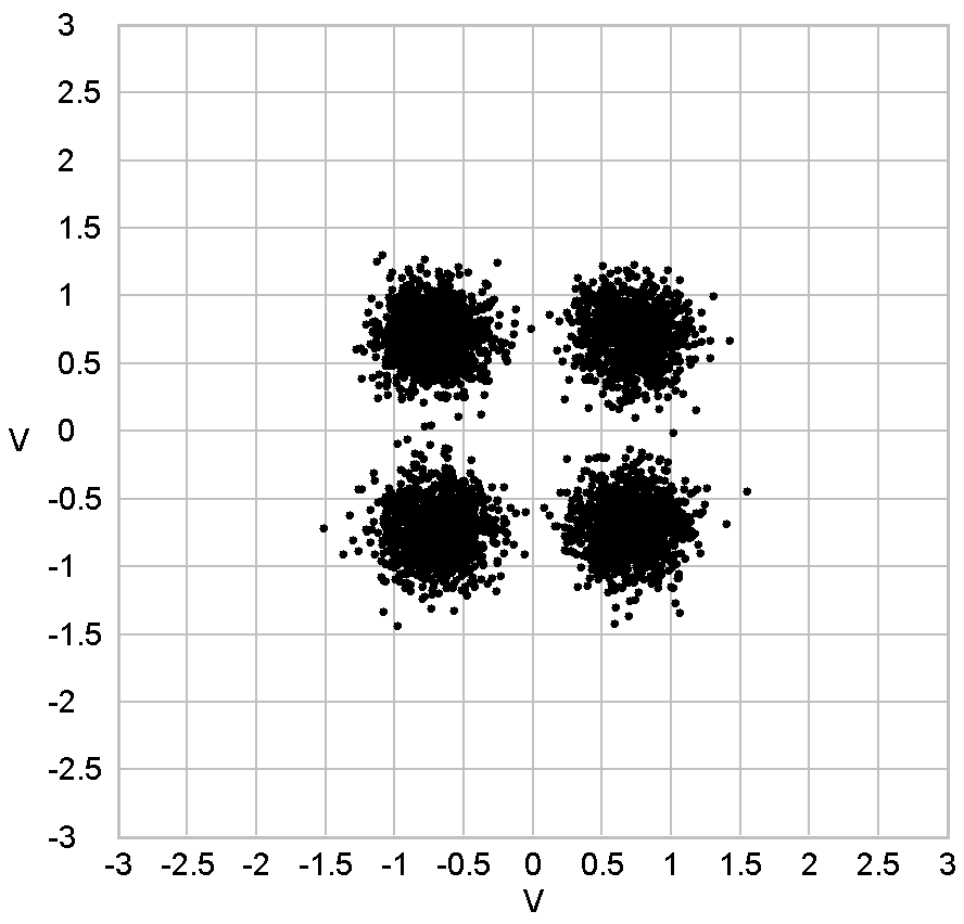
Constellation diagram at 8 dB S/N
ratio.
|

Eye-Pattern at 10 dB S/N ratio
which results in a BER of
|

Constellation diagram at 10 dB S/N
ratio.
|
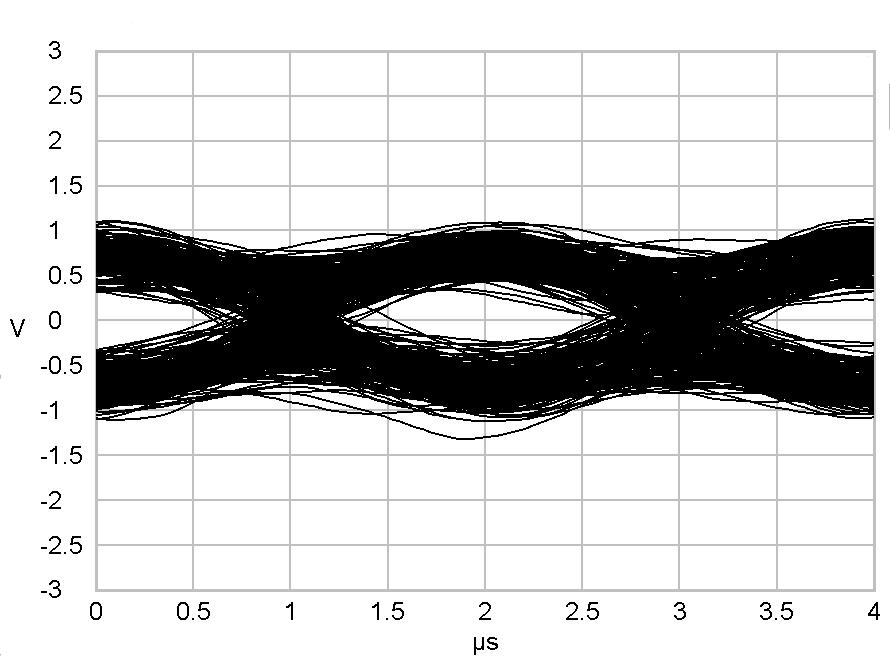
Eye-Pattern at 10 dB S/N ratio
with a halfsine-shaped pulseshaper instead of a rectangle-shaped.
The BER is not affected by the pulseshape.
|
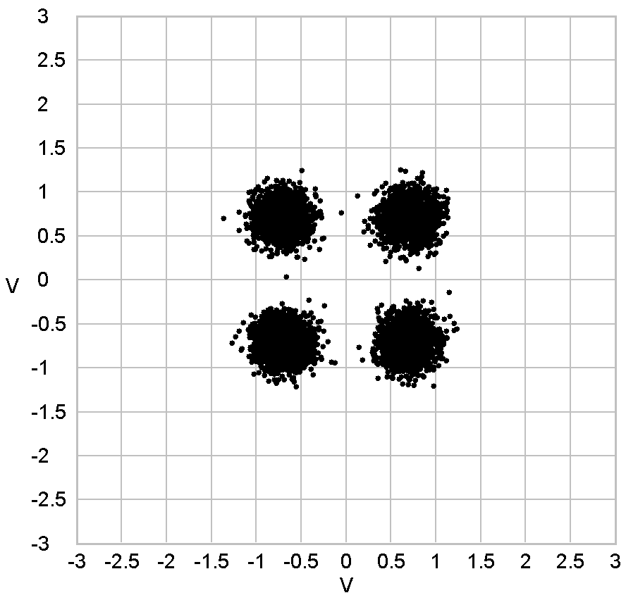
Constellation diagram at 10 dB S/N
ratio with a halfsine-shaped pulseshaper instead of a
rectangle-shaped. The BER is not affected by the pulseshape.
|
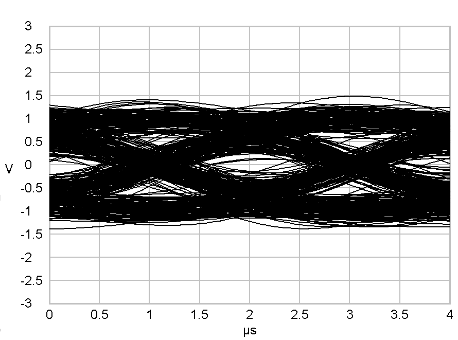
Eye-Pattern at 10 dB S/N ratio
with a sinc-shaped pulseshaper instead of a rectangle-shaped. The
BER is not affected by the pulseshape.
|
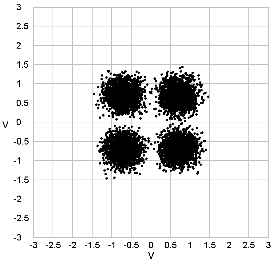
Constellation diagram at 10 dB S/N
ratio with a sinc-shaped pulseshaper instead of a rectangle-shaped.
The BER is not affected by the pulseshape.
|
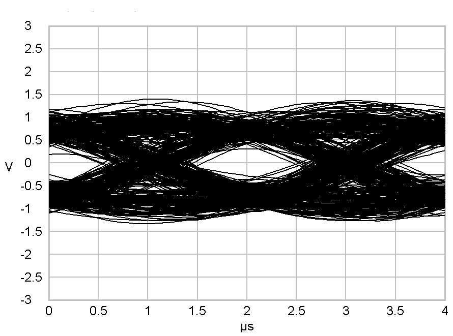
Eye-Pattern at 10 dB S/N ratio
with a root-raised-cosine-shaped pulseshaper instead of a
rectangle-shaped. The BER is not affected by the pulseshape.
|
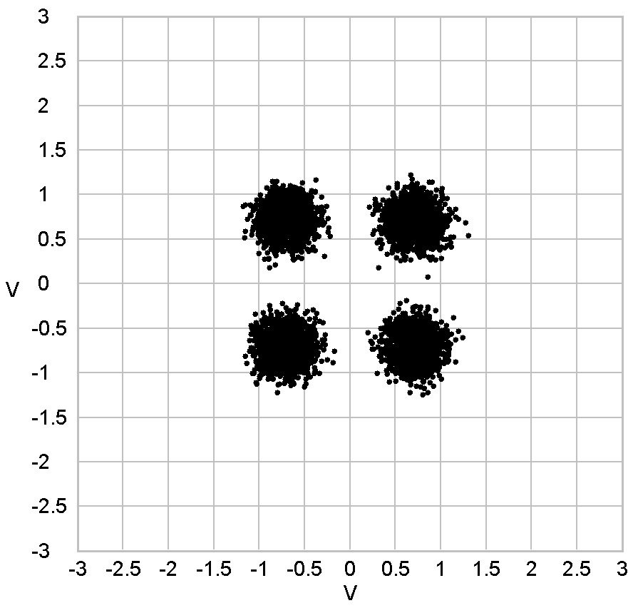
Constellation diagram at 10 dB S/N
ratio with a RRC-shaped pulseshaper instead of a rectangle-shaped.
The BER is not affected by the pulseshape.
|

