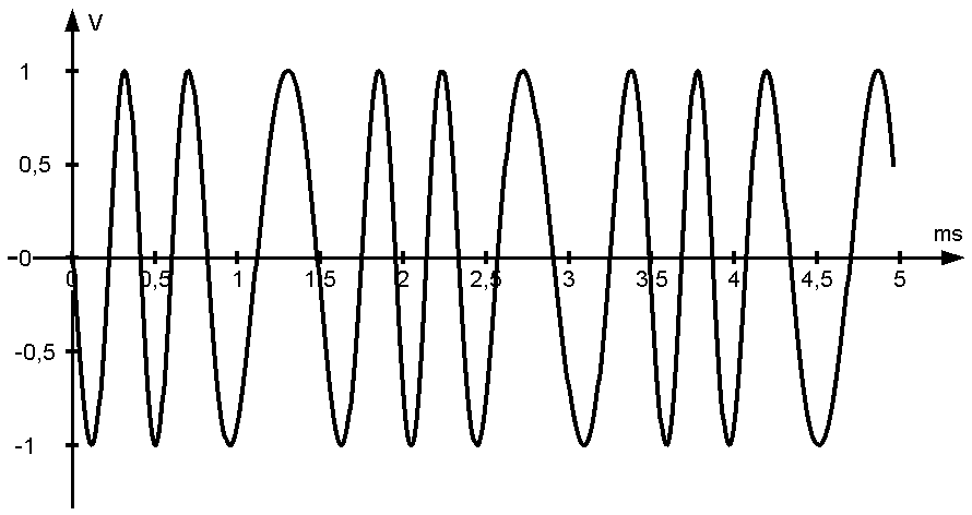
Frequency modulation varies the frequency of a sine wave carrier depending on the source signal.
Transmit signal
The difference between the instantaneous and center frequency of the carrier is proportional to the modulating signal's instantaneous amplitude.
Where
| Modulating signal | Spectrum |
|
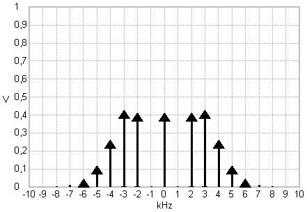
Frequency modulation example - frequency deviation is 1 kHz for a 1V-DC modulating signal
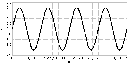
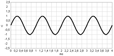
In this experiment a sinewave signal is frequency modulated. Modulating signal and modulator parameters determine the spectrum of the resulting FM transmission signal.
Start
| Modulating signal | Spectrum |
|
|
|
Where
|
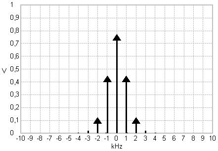
The modulation index for the initial setting is:
|
The modulation index
is the ratio of the maximum frequency deviation of the carrier to the frequency of the sinewave modulating signal.
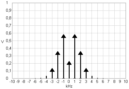
The Bessel function values at the resulting modulation index determine the spectrum of the FM signal.
Experiment
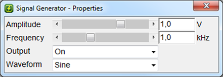
Vary the modulating signal amplitude .
The modulation index is proportional to the modulating signal amplitude. In this setting the amplitude in Volts is the modulation index:
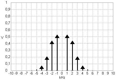
The adjusted modulating signal amplitude determines the spectral amplitudes of the carrier and sideband frequencies. For some values the carrier or specific sideband frequencies disappear. This relates to zero crossings of the respective Bessel function at the corresponding modulation index.
| Modulating signal | Spectrum |
|
|
| When does the carrier frequency disappear?
Modulation index
|
|
| When does the first sideband frequency disappear?
Modulation index
|
|
FM signal spectra for sinewave modulation with different modulation indices.
Note
The carrier frequency is 0 Hz in this setting. It might be changed via the modulator properties.
Next steps
- When do the 2nd and 3rd sideband frequencies disappear?
- Vary the modulating sinewave signal frequency.
- Select different waveforms (signal generator properties) and regard the FM spectrum.
- Use the Bessel functions to determine the spectrum of an FM signal with .
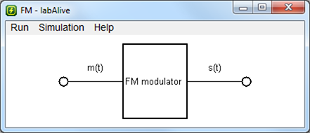
This simulation implements frequency modulation. The FM signal is generated for the chosen modulating signal. Its spectrum is shown in a spectrum analyzer. All parameters of the modulating signal and modulator can be adjusted.
To change the different settings click on the corresponding wiring:
|
Adjust parameters of input signal
|
|
|
Adjust parameters of FM modulator
Left click on FM modulator:
|
|
|
Open measure for transmission signal
Right click on s(t):
|
|
Adjust parameters of FM
 To launch labAlive simulation applications you need a Java Runtime Environment supporting Java Web Start on your system. Here you can get more information about installing the right Java version.
