Fundamentals of OFDM
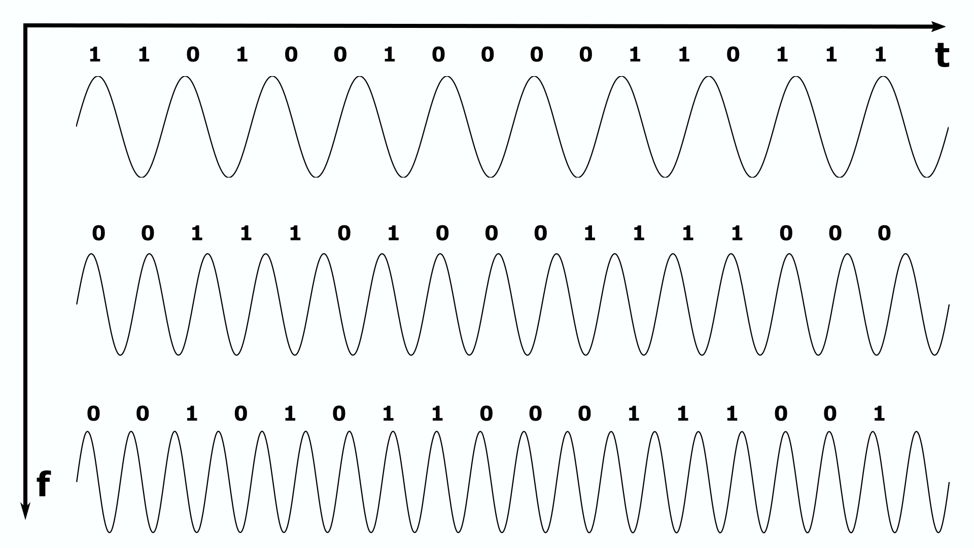
Multi-carrier transmission is one of today’s key technologies for communication systems. They use several sinusoidal waves, which are transmitted simultaneously. The basic idea of multicarrier technology is to fragment a frequency-selective channel into narrowband subchannels such that each of these subchannels becomes approximately non-selective. Furthermore, another principle of multi-carrier transmission is to convert a serial high rate data stream on to multiple parallel low rate sub-streams.
OFDM (Orthogonal Frequency Division Multiplexing) and OFDM-based transmission schemes are dominating current wireless communication standards (WLAN, LTE, DAB and DVB). This is due to the following capabilities and benefits of OFDM:
➤ Robustness against frequency selective fading with the
division of information symbols in parallel narrowband channels
➤ Efficient use of spectrum due to overlapping transmission of
orthogonal parallel narrowband channels
➤ Low-complexity
implementation with the use of Fast Fourier Transforms (FFT)
➤ Low-complexity channel equalization compared with
single-carrier solutions
➤ Robustness against intersymbol
interference (ISI) with the use of cyclic prefix
➤
Robustness against impulsive noise
➤ Simple integration
of multiple-input multiple-output (MIMO) systems in the OFDM
transmitter/receiver chain
➤ Ability to easily integrate
adaptive modulation and coding techniques to efficiently exploit the
radio channel
➤ Provision of direct extension to a
multiplexing scheme with orthogonal division multiple access (OFDMA)
for resource sharing
All in all, compared to single-carrier modulation, OFDM main advantages include high spectral efficiency, robustness against multipath ISI, the simplicity to equalize in frequency domain and the efficiency of applying FFT. Of course, there are also disadvantages like the large Peak to Average Power Ratio, out auf band leakage and the sensitivity to imperfect time and frequency synchronization. The OFDM method is also used for wired transmission and also known as Discrete MultiTone (DMT).
In the following the most important OFDM parameters will be introduced.
As an example, all the parameters will be calculated for DVB-T
transmission.
OFDM Parameters
Subcarrier (DFT/FFT length)
The
total number of subcarriers- or channels
, consists of the number of data-subcarriers
, pilot-subcarriers
and null subcarriers
.
The number of subcarriers
always occurs in a power of two and expresses also the length of the
DFT / FFT.
Data-Subcarrier
The data subcarriers
represent the number of subchannels used for data transmission. In a
simple OFDM structure without virtual subcarriers, the number of
subchannels is equal to the FFT length
.
Pilot-Subcarrier
OFDM
allows the insertion of so-called pilot tones. Pilot tones are
generated by modulating individual subcarriers with specified complex
symbols in a fixed time sequence. The complex values of the pilot tones
are known in advance to the receiver so that an estimate of the channel
inflows or a fine synchronization of the symbol clock can be carried
out in the receiver. Pilot subcarriers
however cannot be used for channel estimation as they are too far apart
for interpolation. These Pilot subcarriers only serve the tracking of
the carrier synchronization.
Null-Subcarrier
Null subcarriers
are mandated in most OFDM wireless standards. These subcarriers are not
occupied but serve to reduce the PAPR of multi-carrier transmission.
This is achieved by reordering the null-subcarriers and
data-subcarriers. In addition, they are used to prevent leakage to
adjacent bands since OFDM Systems usually do not transmit any data on
the subcarriers near the two edges of the assigned band. The unused
subcarriers are also known as guard subcarriers or virtual subcarriers.
Altogether they are called guard band.
Discrete Length of the Guard Interval
A
guard interval, also known as cyclic prefix, is used to prevent certain
transmissions from mixing. They increase the immunity to propagation
delays, echoes, and reflections, against which digital data tends to be
very vulnerable. The length of the guard interval (GI) determines how
susceptible a transmission is. The longer such an interval is, the
better it protects against interference, but the data rate is reduced.
To eliminate ISI, a guard interval is usually inserted at the beginning of each OFDM symbol. In addition, it corresponds to a copy of the last seconds of the basic OFDM symbol. The main idea behind this method is to dimension the GI so large, that the signal components delayed by the channel, only disturb the signal component during the GI duration and not the basic OFDM symbol.
For highly frequency selective channels, the cyclic prefix should increase accordingly. In existing standards like LTE with extended prefix or IEEE 802.11, the cyclic prefix is ¼ of the OFDM symbol duration.
Guard Interval Duration
The exact duration
of the guard interval results in:
Source Symbol Duration
The source
symbol duration
is referred to as the duration of the symbols to be transmitted between
source, channel coder and interleaver.
of the serial data symbols results after serial-to-parallel conversion
in the Total OFDM Symbol Duration.
Symbol Duration
For the
determination of the OFDM time raster, it is very helpful to use the
symbol duration of the transmit signal, also called sampling period,
before the RF modulator, as a reference. The symbol duration is as
follows:
Basic OFDM Symbol Duration
The
long OFDM symbol duration in OFDM systems opens a particularly elegant
way to avoid ISI. As already mentioned, it can be reached by prefixing
a GI. However, the Basic OFDM symbol duration
is without a GI and the number of data subcarriers is equal to the
total number of subcarriers.
Total OFDM Symbol Duration
The
total OFDM symbol duration
is the basic OFDM symbol duration extended by the GI.
Bit Rate
The bit rate
of the OFDM system measures the amount of transmissible messages within
a time interval. If the message set is being quantified with the unit
bit, the term bit rate is used. If the same modulation alphabet is used
for all subcarriers and a transmission with a GI is assumed, then the
bit rate is calculated as follows:
Bit per Symbol
In a multi-level
transmission, a group of
bits are combined into one character (symbol) and transmitted within a
signal step of the duration
. Indeed, there is a correspondance between the number
of bits transmitted per signal step and the required number of steps
of a digital signal.
Code Rate
The code rate
of an optimal, theoretically possible code of infinite length, also
referred to as the channel capacity of the binary symmetric channel,
can be calculated as follows:
Symbol Rate
The Symbol rate
is also known as baud rate within terms of digital communications. It
is the number of symbol changes, waveform changes, or signaling events,
across the transmission medium per time unit using a digitally
modulated signal or a line code.
Subcarrier Spacing
Subcarriers
should only suffer of flat fading. Therefore, subcarrier spacing within
OFDM system must be designed carefully. The spacing
is such that the subcarriers are orthogonal, so they won?t interfere
with one another despite the lack of guard bands between them. This
comes about by having the subcarrier spacing equal to the reciprocal of
basic OFDM symbol duration, which means, that the spacing is directly
related to the basic OFDM symbol duration.
Bandwith Efficiency
Bandwidth
efficiency
, also known as Spectral Efficiency, is an important piece of
communications technology that specifies how many units of information
per hertz are transmitted within the available bandwidth. It is thus
the ratio of the data transfer rate to the occupied bandwidth, which is
given in bit / s / Hz. The spectral efficiency depends on the used
modulation method and the coding. Since the available bandwidths cannot
be arbitrarily increased, the frequency economy and the modulation
method used are decisive for spectral efficiency. The spectral
efficiency is limited by the signal-to-noise ratio (SNR). The
relationship between bandwidth and signal-to-noise ratio is determined
by the Shannon-Hartley law. Thereafter, the channel capacitance
increases linearly with the bandwidth and is affected logarithmically
by the signal-to-noise ratio. With modern modulation techniques, such
as OFDM and complex antenna constellations, such as multiple input
multiple output (MIMO), the S / N ratio, the bandwidth efficiency can
be improved. The bandwidth efficiency is adversely affected by the GI
and reduced proportionately because the channel is occupied during the
GI without data being transmitted. On the receiver side, the GI is not
used in terms of detection, but the proportion of signal energy is
lost.
Nyquist Bandwith
The Nyquist
bandwidth
is the bandwidth required for optimal pulse shaping. Although the
symbols of the GI do not transmit payload, they proportionately consume
transmission bandwidth. The required Nyquist bandwidth thus results
from the number of subcarriers and the respective subcarrier spacing.
Learn more about OFDM and it’s most important parameters by checking out the corresponding experiment!
Calculation of WLAN IEEE 802.11g OFDM Parameters
Determine the missing parameters for IEEE 802.11g (WLAN) in the table below by using the necessary formulas given in the corresponding tutorial to complete the parameter set of this common wireless transmission standard.
Parameter |
value for IEEE 802.11g |
Comment |
| Number of Subcarriers | 64 | |
| Number of Data Subcarriers | 52 | |
| Number of Pilot Subcarriers | 4 | |
| Number of Null Subcarriers |
|
|
| Discrete Length of GI | 16 | |
| GI Duration |
|
|
| Source Symbol Duration |
|
|
| Symbol Duration |
|
|
| Basic OFDM Symbol Duration |
|
|
| Total OFDM Symbol Duration | ||
| Bit Rate |
|
|
| Bit per Symbol | 6 | |
| Code Rate | 0,75 | |
| Symbol Rate |
|
|
| Subcarrier Spacing |
|
|
| Bandwidth Efficiency |
|
|
| Nyquist Bandwidth |
|
|
| Nyquist Bandwidth with DC Subcarrier |
|
|
Parameter |
value for IEEE 802.11g |
Comment |